
Hydraulic Jack with Load Indicator Calibration
(Load Cell & Gauge — ISO 7500-1 / IS 1828 Part-2)
Hydraulic jack calibration service with Load Indicator is carried out to verify the accuracy of applied load and indicated force values used during field and laboratory testing. Hydraulic jacks with load indicators are widely used in plate load tests, pile load tests, structural loading, and geotechnical investigations, where precise load measurement is critical for safety and design validation.
What is the Hydraulic Jack with Load Indicator Calibration?
Hydraulic Jacks with Load Indicators are the primary load application and measurement system in field load tests — pile vertical load tests (IS 2911), slab load tests, plate load tests (IS 1888) and structural proof load tests. The hydraulic jack applies force; the load indicator (pressure gauge × calibrated area, or bonded strain gauge load cell) measures it. Both systems require regular calibration for accurate load test results.
At Global Lab, hydraulic jack and load indicator calibration per IS 1828 Part-2 (Calibration of Testing Machines) and ISO 7500-1 uses NPL-traceable reference load cells in a calibration frame to apply known loads to the jack and compare against the jack's gauge or load cell display. A jack-specific calibration chart (force vs gauge pressure) is issued — used directly on-site during load testing.
Non-Destructive
Fast Turnaround
NABL Certified
Pan-India Coverage
Digital Reporting
High Accuracy
Hydraulic Jack with Load Indicator Calibration — Site Images
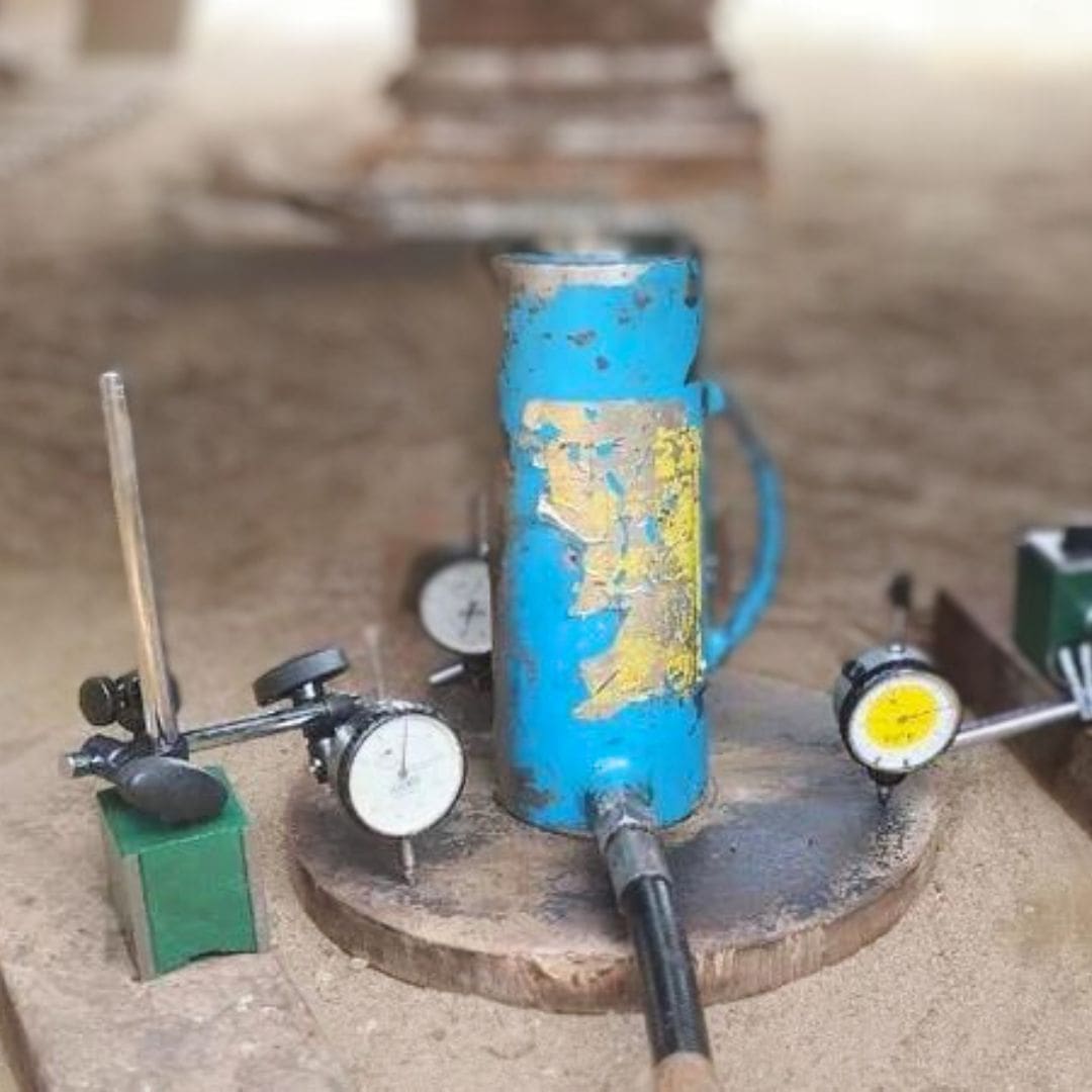
How the Hydraulic Jack with Load Indicator Calibration is Conducted
-
1
Surface Preparation
A shallow groove (approx. 25mm deep) is cut into the concrete surface using a diamond-tipped cutting tool. The surface is cleaned of dust and debris. -
2
Insert Disc Placement
A specially designed steel insert disc is placed into the groove. A thin rod connects the disc to the pullout apparatus above the surface. -
3
Hydraulic Pullout Force Application
A hydraulic jack applies a steady, controlled pullout force to the insert disc via the reaction ring resting on the concrete surface. -
4
Failure Load Recording
The maximum force at which the concrete cone is extracted is recorded. A digital load indicator provides real-time readings with data logging. -
5
Strength Calculation & Reporting
The pullout force is correlated to cube compressive strength using established calibration curves. NABL-accredited reports are issued via Autovity QLMS.
Applicable Test Standards
| Standard | Title | Scope | Type |
|---|---|---|---|
| IS 1828 Part-2 | Methods for Calibration of Testing Machines for Tensile Testing | UTM Calibration | Indian Standard |
| NABL-141 | NABL Policy on Metrological Traceability of Measurement Results | Traceability | NABL |
| ILAC P10 | ILAC Policy on the Traceability of Measurement Results | Traceability Policy | ILAC |